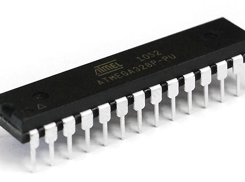
Before you can program or interact with a microcontroller in any way it is important to understand its features and specifications. Just like in a car it is important to know where the gas cap is and which pedal is the gas and break in a microcontroller you must know where to apply how much power to turn it on and which pins to use to communicate with it. For this section I will use the Atmega328p by Atmel as an example of how a microcontroler's datasheet can help you. A great example of using a microcontroller datasheet can be found here when I design and built the board I am programming this week. |
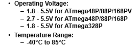

The datasheet for any microcontroller can usually be found be simply searching the name of your microcontroller followed by the word "datasheet" in google. Once you have found the datasheet for your microcontroller you can download the pdf and open it. The first thing you should is spend some time on the front page of the datasheet. This page is usually labelled "Features" or something similar. On this page you can find important information about the microcontroller you are going to be using. This includes, but is not limited to, operating voltage range, operating temperature range, special features or capabilities you may want to utilizes, etc. |
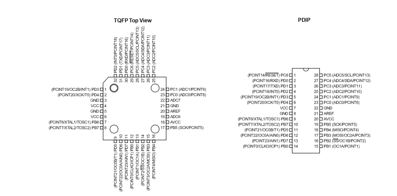
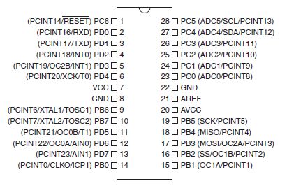
The next thing you should look for is the packages and pinouts section as seen above. This section will show the different packages or physical layouts your the microcontroller is available in. You can locate the package you have or intend to use and than look at the pinouts. These tell you which pins can be used as power in, control, clock, input, output, etc. For power you will want to locate the pins labeled vcc and ground. For the Atmega328p PDIP package these are primarily pins 7, 8, 20, and 22. For programming with a standard ISP you will want to locate the MISO, VCC, SCK, MOSI, RST, and GND pins. On the Atmega328p PID package these are pins 18, 7, 19, 17, 1, and 8 respectively. |
After that the datasheet can help you as much or as little as you choose. You can be done right then and there and get on to programming or you can dive deeper and learn more about the chip and how it functions. Datasheet often provide other information such as block diagrams or the chips internal structure, comparison tables showing the microcontroller and other similar microcontrollers (this coule help you find a chip better suited to your needs), etc. |

In this section I will go through how to program AVR micro controllers through Linux. I am using Linux Mint and will assume you are to, though most of these steps should work for other Linux distributions. On Linux the process is suprisingly simple and straightforward. |
This is a good time to access the datasheet of your microcontroller as seen talked about in the previous section. It is a good to keep an image of the pinouts of the microcontroller you are working with close by for reference. |
Most of the work will be done in terminal through AVRDUDE and a GCC compiler. If you have not used your computer to program AVR micro controllers before and are just getting started the first step is to set up teh toolchain for programming. Simple type the following command into terminal. |
sudo apt-get install avrdude avrdude-doc binutils-avr avr-libc gcc-avr gdb-avr |
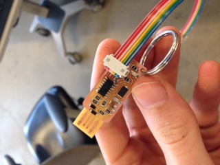
Next get an AVR programmer of your choice. I like to use the Fab ISP as well as the Atmel ICE programmers. Plug the programmer into your computer and into your circuit. |
Once that is setup check that your computer recognizes your programmer (you can use the command lsusb to check for usb devices in Linux). Then type the following command into terminal. |
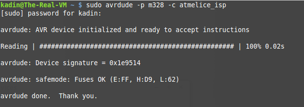
sudo avrdude -p m328 -c atmelice_isp |
If you are not using the Atmega 328 and an Atmel ICE programmer you can simply change the 328 to your chip (ex. Atmega168p would be m168p) and the atmelice_isp to your programmer (ex. usbtiny). If all goes well you should see the same response as in the image above. |
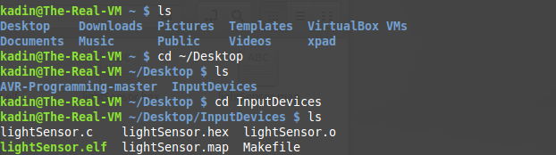
The next step is navigating to the folder that contains your makefile and software. This week I am using my code from my Input programming week which can be found here. You can use cd ... to move into folders and ls to view what each folder or directory contains. Here is a generic makefile that I have customized to meet my needs. Feel free to use this one just remember to change the programmer and processor in the makefile if you are using different ones than me. Inside of the make file I have left some comments as well as imported some comments from other examples that I have found very helpful in decifering makefiles. It is a good idea to read through them and start to understand what is going on. |
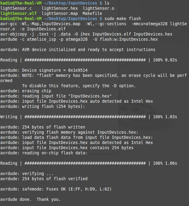
Now onto the final step. Once you are in the folder that has your code and makefile simple type the following command into terminal. |
make flash |
hopefully you get a similar response to the one above. After this step is done your file should have successfuly been pushed to your micro processor. |

In this section I will be programming my PCB board from week 6 using an Atmel ICE programmer and Atmel Studio. |
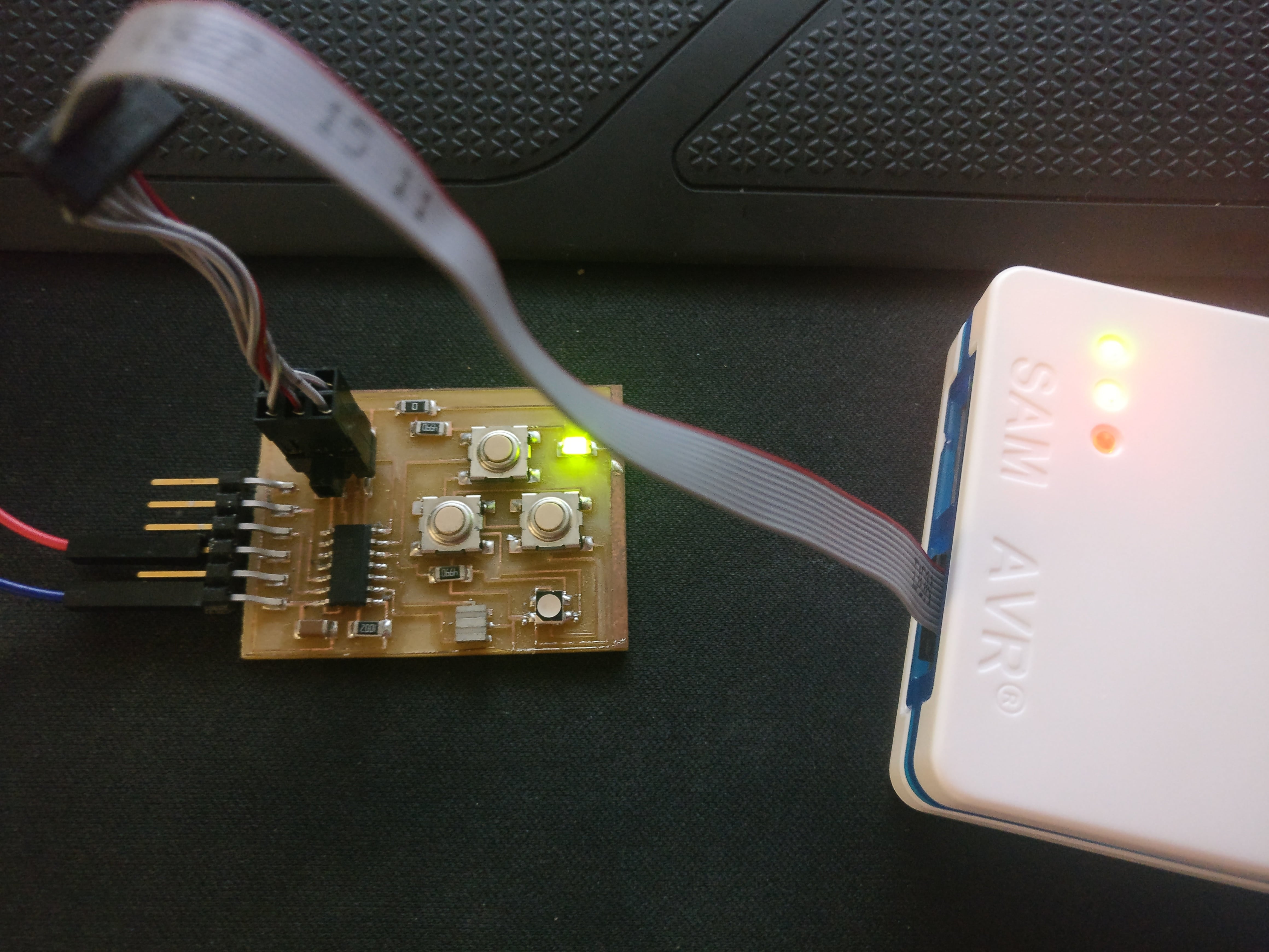
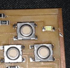
The first step, similar to programming with AVRDUDE, is to plug the programmer into your computer and the programming board. Remember, if you are using an Atmel programmer you will also have to plug your programming board into an external power supply as seen above. |
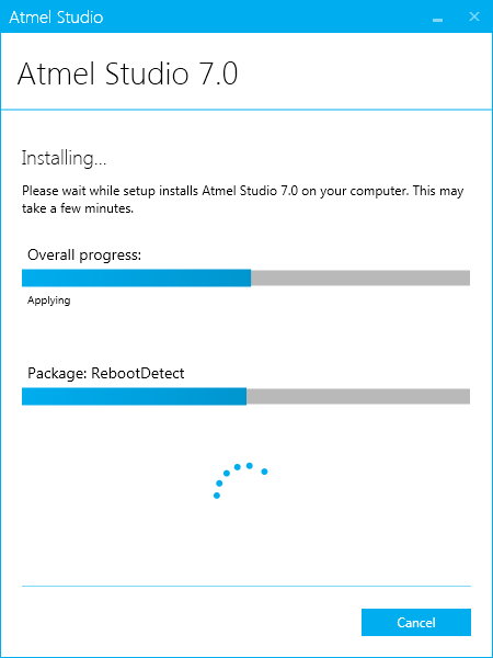
The next step is to install Atmel Studio. It is available for free on Atmel's website. |
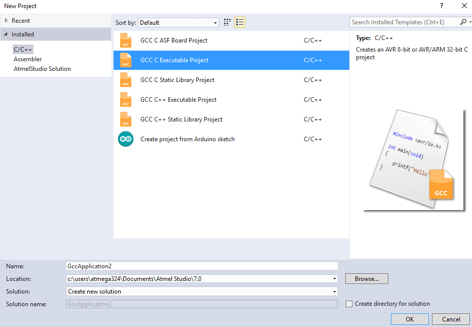
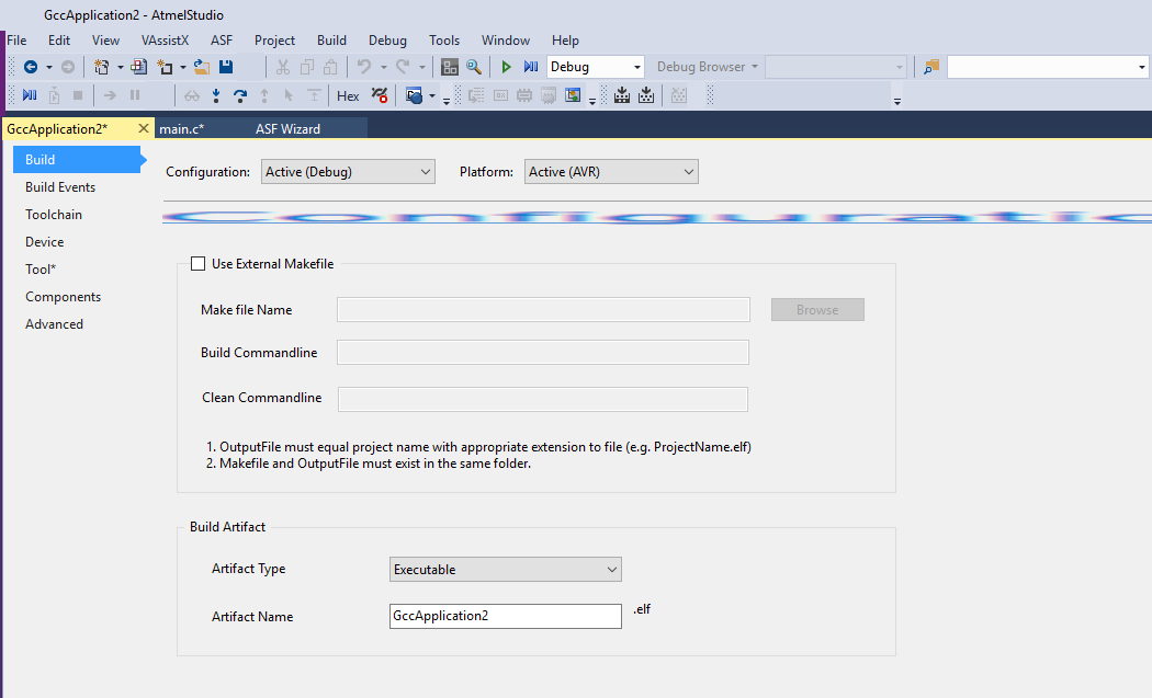
After Atmel Studio has installed open the application and go to File>New>Project... then select "GCC C Executable Project" as seen above, and remember to unselect "Create directory for solution" in the bottom righthand corner of the popup window. You will then be prompted to select the microcontroller you are going to be programming, in my case Attiny44A, and then the file will be created. |
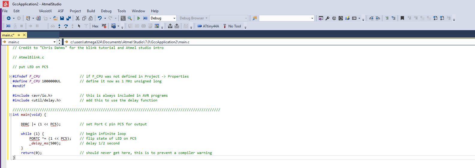
Once your file is created you can write your program in the space provided as seen above. This is the equivilent to the lightsensor.c code used in the AVRDUDE example above. The code is used as seen above can be downloaded at the bottom of this page. |
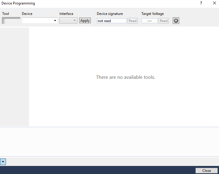
The next step is to click on the Atmel chip with a lightning bolt symbol in the upper right of the screen to open the flash settings. This button will bring up the above window. Select your programer, microprocessor, and interface from the drop down menus and then click "Apply". Next read the target voltage (you should get about 5v). If the target voltage read is successful click "read" device signature. If you get a device signature it means the programmer is communicating with the chip and you are ready to move on. At this point it does not matter what the device signature is as long as there is one. Close the menu. |
Next, select the "Project" dropdown menu from upper lefthand side of the screen and then select "AtmelBlink Properties...". Remember "AtmelBlink" may change based on the name of your file. In the pop up window that appears, as seen above, click on the "Tools" page. In the tools page select your programmer and interface just as you did in the last step. Then close the pop up menu. |
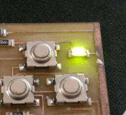
Finally, hit Ctrl and F5 to flash the chip. If all goes well the output menu at the bottom of the screen will say "Build Succeeded" and your board will be running the program. In my case this meant blinking the LED on my board as seen above. |